Prox Switch Wiring Diagram

3 Wire Proximity Switch Wiring Diagram Google Search With

Iv E10 Npn Wiring Diagram Ece With Images Diagram Electrical

What Is The Difference Between Pnp And Npn Con Imagenes

What Is The Difference Between Pnp And Npn With Images Learn

Basic Operating Principle Of An Inductive Proximity Sensor

Ford Transit Custo Towbar Wiring Diagram In 2020 With Images

A wide range of metal objects.
Prox switch wiring diagram. 3 khz ss pur 22 awg 1 nbb2 12gm50 e0 2 flush npn n o. This wire is noted on the i o module s wiring diagram. 3 wire and 4 wire dc. Wiring diagrams show the hook up offour sensors with npn and pnp outputs.
Negative lead is black on m12 quick disconnect cables and blue on axial cables. Many proximity switches though do not provide dry contact outputs. I show you how to test and interface the sensor. And stable proximity alarm which may be built at very low cost.
The schematic diagram symbol for a proximity switch with mechanical contacts is the same as for a mechanical limit switch except the switch symbol is enclosed by a diamond shape indicating a powered active device. Collection of 2 wire proximity sensor wiring diagram. If it is not grounded this range is reduced to about one third. Pnp sensor outputs switch in a positive fashion.
Click on this link. They can come in all different technologies such as inductive photoelectric and capacitive just to list a few although the sensor technology may differ all 3 wire sensors are wired the same a three wire sensor has 3 wires present. Here s a simple way remember how to wire up a 3 wire dc pnp or npn sensor. If the negative terminal is grounded it will detect the presence of a hand at more than 200mm.
Wiring diagram when sensor is wired in sourcing mode used with a sinking module. It shows the components of the circuit as streamlined shapes and also the power as well as signal connections in between the devices. 12 nj2 12gm40 e2 2 flush pnp n o. 3 wire and 4 wire dc inductive proximity sensors 3 wire and 4 wire dc 89 2 meter cable models dia.
A short tutorial on a 3 terminal pnp capacitive proximity sensor. The proximity switch emits a loud falling siren when a body is detected within its range. Two three or four wire proximity sensors contain a transistor oscillator and a. 1 5 khz ni brass pvc 26 awg 2.
A wiring diagram is a streamlined standard photographic depiction of an electrical circuit. Pnp switched positive npn switched negative switched refers to which side of the controlled load relay small indicator plc input is being switched electrically. This means that multiple sensors can be connected to an input card with all sensor negative wires to one common wire. Three wire sensors are used in various applications from detecting parts to locating position of the actual machine.
Mm model number range mm mounting electrical output switching frequency barrel material cable jacket size dwg.

Best Of Wiring Diagram Zx7r Troubleshooting Diagrams

Pin Di Electronica

Wrg 3714 Home Alarm System Wiring In 2020 Alarm Systems For Home

Bmw E39 Wiring Diagram Yirenlu Me Adorable Blurts Within At Bmw

Staircase Timer Wiring Diagram Using On Delay Timer And Relay

Fungsi Pengunci Dan Pengaman Kontaktor Magnet Pada Sistem Kontrol

Control Stepper Forward And Reverse With Proximity Limit Switch

Ladder Diagram Symbols Memes Diagram Ladder Logic Symbols

Pin On Power Electronics Projects

Pin Na Doske Cadilac
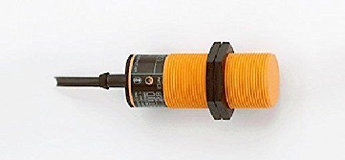
Ifm Ii5436 Ii 2015 Frkg Ii 5436 Inductive Proximity Sensor Dc Pnp

1991 Mazda B2600 Headlight Drl Wiring Diagram

Iv E10 Npn Wiring Diagram Ece Diagram Control Panel Wire
