Proportioning Valve Wiring Diagram
Classic Performance Proportioning Valve Kit Installation

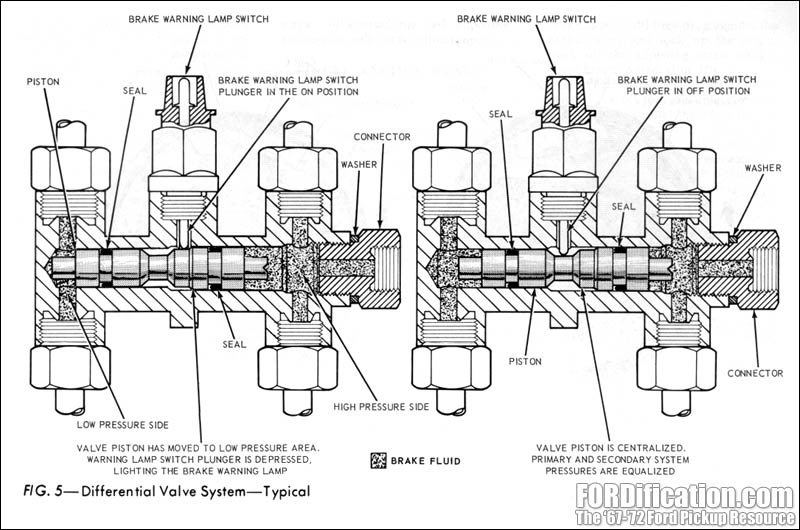
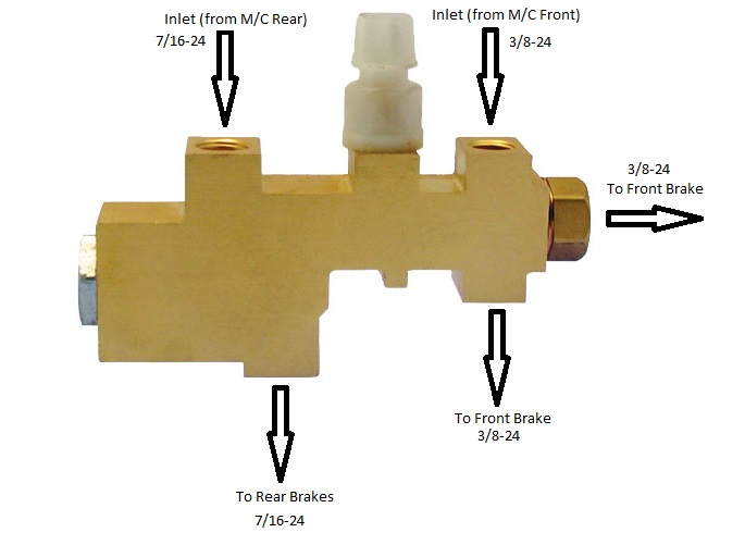
66 77 Early Ford Bronco Disc Brake Proportioning Valve Diagram
Gm Proportioning Valve Wiring Hot Rod Forum Hotrodders
F1a27 Wiring Diagram For Brake Proportioning Valve Wiring Resources
Brake Proportioning Valve Replacement
Proportioning Valve Issues The 1947 Present Chevrolet Gmc
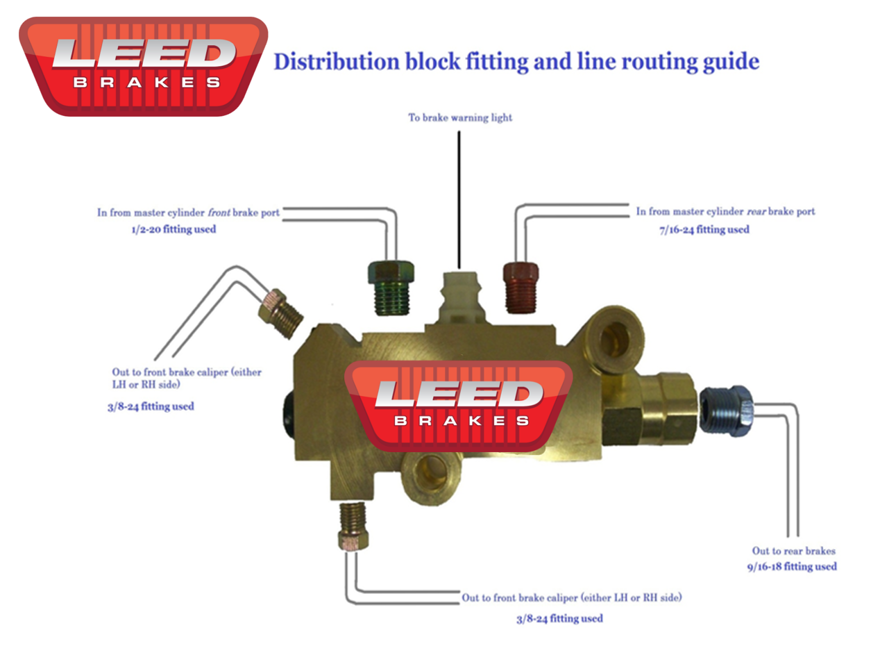
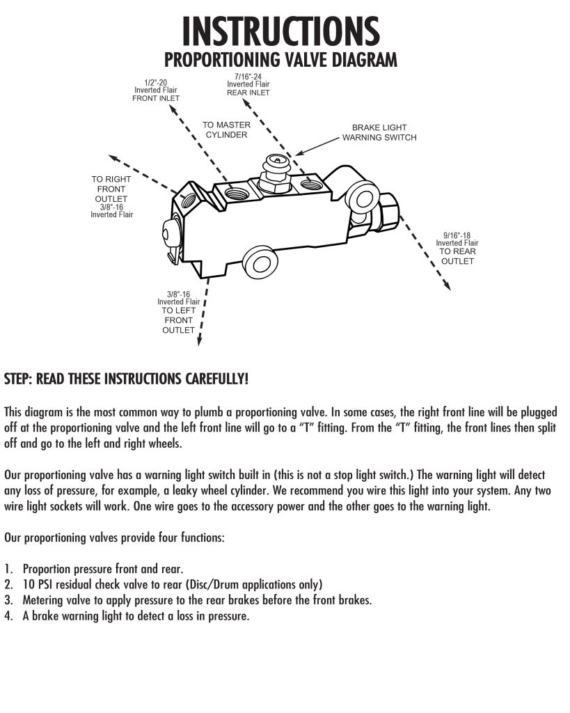
This diagram is the most common way to plumb a proportioning valve.
Proportioning valve wiring diagram. Adjustable proportioning valves are typically used in an aftermarket brake system where the vehicle owner might need to adjust the braking pressure going to the rear brakes. There are two proportioning valve lines that connect to the master cylinder provided in our kits. Connect the other pressure switch wire to the lead wire going to the brake lights. Select the location for bulkhead mounting the proportioning valve that allows easy access to the adjusting handle knob.
Be sure the brake lights are properly grounded and all connections are secure and insulated. The outlet of the proportioning valve is connected to the line leading to the caliper s. Dot 3 4 and 5 1. Inlet of the proportioning valve.
E proportioning valve adjustment 1 the proportioning valve in the prop block will be used to adjust the rear brake pressure of the vehicle the objective is to balance the pressure of the rear brakes to the front so that under hard braking the rear brakes do not lock up before the fronts. Classic performance products 175east freedom avenue anaheim ca 92801. Proportioning valve plumbing diagram. The first is a 90 degree bend with one leg longer than the other.
From the t fitting the front lines then split off and go to the leftand right wheels. The wilwood proportioning valve block is fully compatible with all types of brake fluid including dot 3 4 5 and 5 1 fluids. Make sure that the location allows room for the hydraulic lines and access.

Brake Proportioning Valve Function Diagnosis
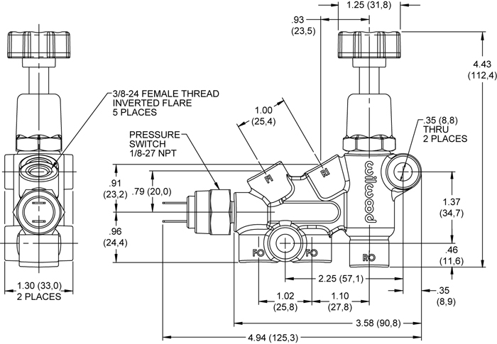
Wilwood Disc Brakes Master Cylinders Description

Adjustable Proportioning Valve Pirate 4x4
Brake Line Installation For 75 Dart Proportioning Valve For A
Prop Valve Questions The 1947 Present Chevrolet Gmc Truck
Tech Information Archives Performance Online Inc

Brake Proportioning Valve Question The Ford Torino Page Forum
Help Proportioning Valve Issues Ford Truck Enthusiasts Forums
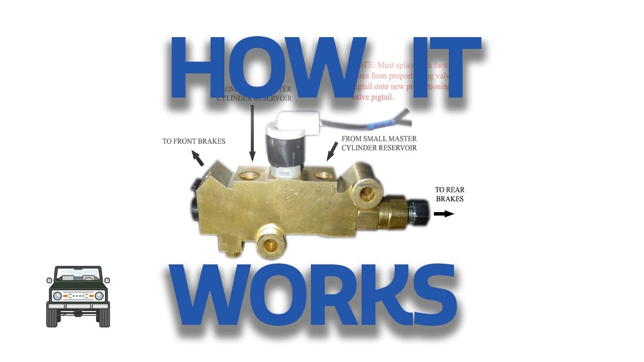
Proportion Valve How It Works Youtube

Disc Disc Brake Proportioning Valve D And C Extreme

Sonnection Diagram Proportioning Valve Alfa Romeo Forums
Drum Drum Brake Proportion Valve Troubles Jeepforum Com

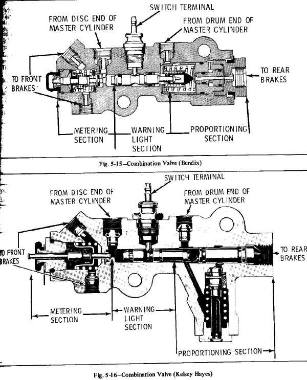
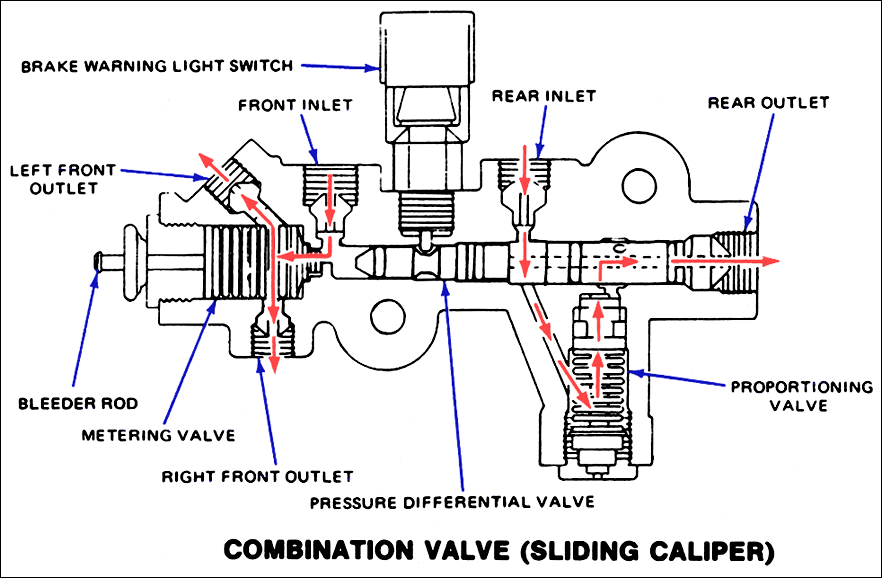
The Combination Valve How Master Cylinders And Combination
