Problems Of Block Diagram Reduction In Control System
Control Systems Block Diagram Reduction Tutorialspoint
Control Systems Block Diagrams Tutorialspoint
Problem 1 On Block Diagram Reduction Youtube

Block Diagram Reduction Youtube

Block Diagrams Of Control System Electrical4u
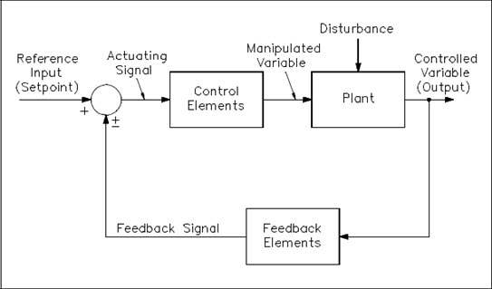
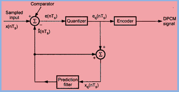
The Basics Of Process Control Diagrams Technology Transfer Services
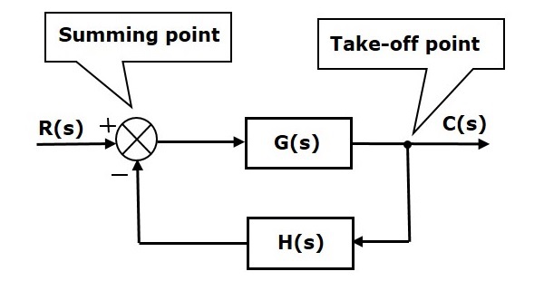
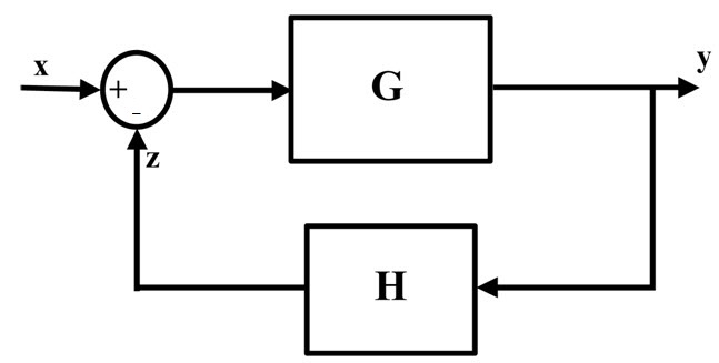
Single block diagram representation.
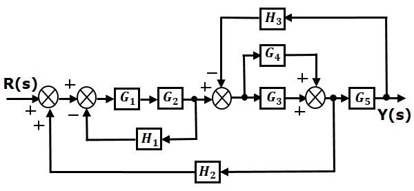
Problems of block diagram reduction in control system. Eliminating the minor feedforward path we obtain figure 3 45 b which can be simplified to. Ece 680 modern automatic control routh s stability. Step 3 get the overall transfer function by adding all those transfer functions. Thus in simple terms block diagram is pictorial representation of entire system.
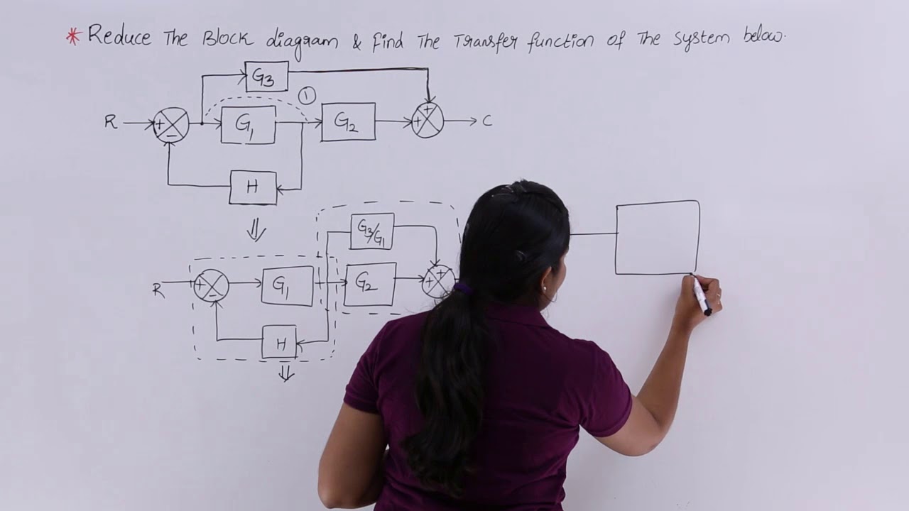
Cascade series connections figure 6. In other words practical representation of a control system is its block diagram. Example 9 find the transfer function of the following block diagrams 2g 3g1g 4g 1h 2h sy sr 3. Reduction of the block diagram shown in figure 3 44.
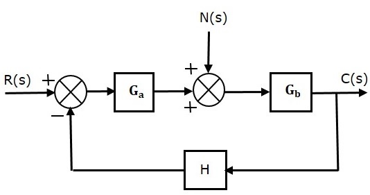
Step 1 find the transfer function of block diagram by considering one input at a time and make the remaining inputs as zero. Step 2 repeat step 1 for remaining inputs. Block diagram algebra for summing junctions. G s c s r s where r s laplace transform of the input variable.
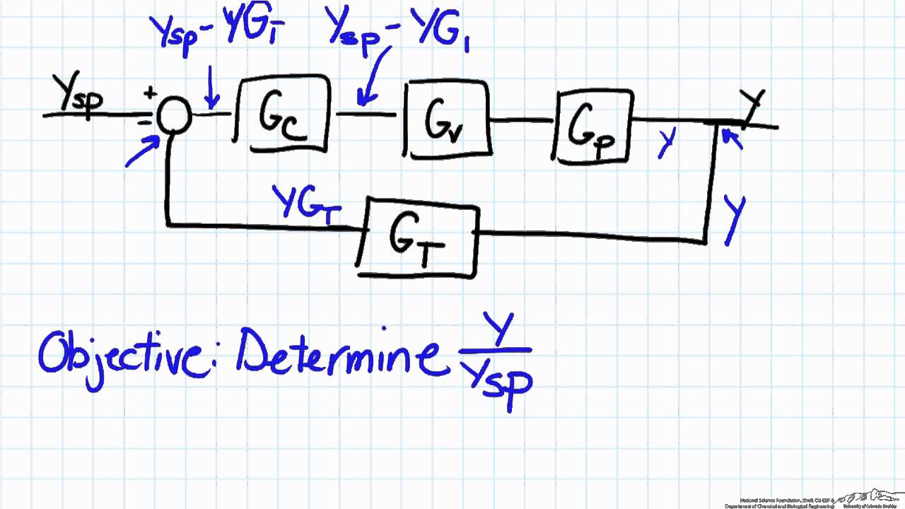
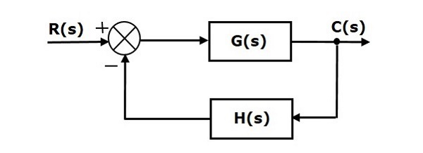
Note follow these steps in order to calculate the transfer function of the block diagram having multiple inputs. B tech e e uid u41000000484 email. Hello friends in this blog article we will learn block diagram algebra in the control system. Block diagram of a closed loop system with a feedback element.
The block diagram reduction process takes more time for complicated systems. It will include block diagram reduction rules some block diagram reduction examples and solutions. In this video i have explained two problems on block diagram reduction in control system. Block diagram simplifications figure 5.
We know that the input output behavior of a linear system is given by its transfer function. It is easier and better to derive the transfer function of the control element connected to the system separately. Figure 3 46 block diagram of a system. It is not always convenient to derive the entire transfer function of a complex control system in a single function.
Block diagram reduction figure 1. Block diagram examples 1. Moving pickoff point a ahead of block 2g 2. Thus in order to analyse complex control systems and hence complex block diagrams it is much desirable to reduce the block diagram in simple terms by means of block diagram reduction techniques.
The block diagram of figure 3 44 can be modified to that shown in figure 3 45 a.
Simple Block Diagram Analysis Youtube
Control Systems Feedback Tutorialspoint
Control Systems Steady State Errors Tutorialspoint

Block Diagrams An Overview Sciencedirect Topics

Control System Closed Loop Open Loop Control System Electrical4u

Control Tutorials For Matlab And Simulink Simulink Basics Tutorial

Block Reduction Technique Blocks Electrical Engineering Techniques

Visual Problem Solving With Mind Maps And Flowcharts With Images

Types Of Controllers Proportional Integral And Derivative
Negative Feedback System
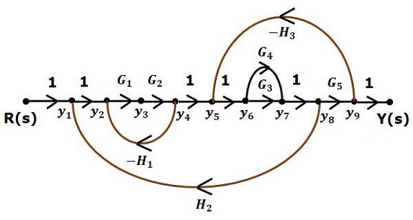
Control Systems Signal Flow Graphs Tutorialspoint
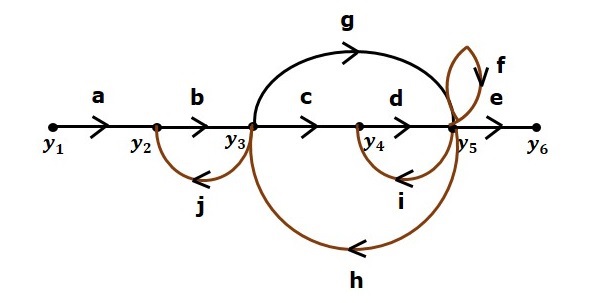
Mason S Gain Formula Tutorialspoint

Transfer Function Of Control System Electrical4u
